Acoustic Sensor
Note: The code snippets in this article are intended for XDK-Workbench versions 3.4.0 and higher.
This chapter gives a small overview about the Acoustic Sensor AKU340, which is part of the sensors on the XDK. It shows how to initialize and read data measured by the AKU340, and it also explains how to calculate the sensor’s analog sound pressure. For more information about the AKU340, please refer to the corresponding datasheet.
- Initializing the acoustic sensor
- Reading data from the acoustic sensor
- Converting the data from the acoustic sensor into sound pressure
- Converting the data from the acoustic sensor into sound pressure level
- Calculating the sound intensity over the sound pressure level
- Calculating the Fast Fourier Transformation
- Full Code Example
- Sample Noise sensor application Basic
Initializing the acoustic sensor
Before we start with the implementation of the acoustic sensor, the sensor’s header file needs to be included, which is XDK_NoiseSensor.h. This header file provides the complete functionality to access the acoustic sensor. Afterwards the function NoiseSensor_Setup() is used to initialize the sensor with a certain sampling frequency. An appropriate value for the sampling frequency would be, for example, 22050 Hz.
#include "XDK_NoiseSensor.h"
// other interfaces here

NoiseSensor_Setup(22050U);
For the initialization of the acoustic sensor, which sets certain parameters for the acoustic sensor, an enabling of the sensor is required. The enabling itself sets the sensor into the fully operational state and starts the sampling process of the sensor. For that, the function NoiseSensor_Enable() needs to be called.
NoiseSensor_Enable();
Reading data from the acoustic sensor
Reading data from the acoustic sensor can only be done over the function NoiseSensor_ReadRmsValue(). The function provides the root mean square value calculated over 256 samples taken from the acoustic sensor in its physical voltage representation. For receiving the data a variable of the type float and a timeout needs to be passed into the function NoiseSensor_ReadRmsValue(). While the variable for storing the data needs to be passed as reference to the function, the timeout can simply be passed as call by value. Furthermore, the timeout will be used to return from the blocked state. Currently is no calculated root mean square value for the acoustic sensor available. A default value of 10 milliseconds for the timeout should be sufficient to use the function.
float acousticData;

NoiseSensor_ReadRmsValue(&acousticData,10U);
Converting the data from the acoustic sensor into sound pressure
While the API for the acoustic sensor does not provide the functionality to convert the received root mean square value into the actual physical sound pressure value, this can be made with a slight approximation of the sensitivity value of the AKU340. Please note that the sensitivity value for the AKU340 has a tolerance of +-2 dBV/pa over the frequency range from 60 Hz to 12.5 kHz. This is sufficient, since every microphone has a norm tolerance of maximal +-3dB over the complete frequency range. Furthermore, the sensitivity of -38 dBV/pa is only exactly valid for the frequency of 1 kHz. For other frequencies this might lead to errors in the measured magnitude, since then the tolerance of +- 2 dB needs to be taken into account.
A first easy approximation can be made by declaring this value static as -38 dBV/pa.
An implementation for converting the received acoustic sensor data into sound pressure can look as follows.
#include "math.c"
// other interfaces here

const float aku340ConversionRatio = pow(10,(-38/20));

float calcSoundPressure(float acousticRawValue){
    return (acousticRawValue/aku340ConversionRatio);
}
First, the sound pressure to output voltage conversion ratio of the AKU340 is calculated using the math.c library into a linear value from its logarithmic data sheet specification. Then, the implementation of the function calcSoundPressure() is used to calculate the sound pressure representation in millipascal by using the previously calculated conversion ratioAKU340 and the passed root mean square voltage value read from the acoustic sensor.
For convenience, please note that the AKU340 integrated on the XDK can only be used as ambient noise sensor since only the positive sine wave of the output signal of the AKU340 can be sampled and the negative one is clipped off by the XDK’s internal ADC. A usage as microphone is, unfortunately, not possible due to the lack of information from the negative sine wave of the output signal of the AKU340.
Converting the data from the acoustic sensor into sound pressure level
Sometimes, only converting the sound pressure might not be enough to conduct analysis in greater detail, since the human ear, for example, does recognize sound pressure logarithmic. That means, small changes are not noticed with great detail, while great changes are noticed very detailed. As such, it is very helpful to convert the received measurements of the acoustic sensor into the sound pressure level.
The sound pressure level covers a logarithmic scale to represent the sound pressure of measured sound pressure relative to a reference sound pressure. The logarithmic scale gives changes about tenth power a certain level of information.
For that, the following equation is used, where p is the sound pressure of the sound wave and p0 is the reference sound pressure:
SPL = 20*log10(p/p0) dB
Since the equation for calculating the sound pressure level is using a reference value, the output of it is always an absolute value relating to a defined reference value.
Usually, 20 µPa are used as reference sound pressure, since this is the threshold of a least heard sound event a human ear can detect. A typical range for the sound pressure level is set by 20µPa to 200 Pa, which is expressed in dB as the range from 0 to 140 dB, while 140 dB the pain threshold for the human ear.
The following table gives an indication of how high certain sound pressure is described in sound pressure levels.
| Sound pressure level | sound pressure source |
|---|---|
0 dB | Exceptionally quite |
10 dB | Leave swishing |
20 dB | Silence in sound studio |
25 dB | Breath sound |
30 dB | Whispering |
35 dB | Room ventilation |
40 dB | Concentration disturbance threshold |
45 dB | Quiet apartment |
50 dB | Birds twittering |
55 dB | Radio/TV in low volume |
60 dB | Normal conversation |
65 dB | Heart disease, cardiovascular disease increase |
70 dB | Passenger car |
75 dB | High traffic, turnery, truck |
80 dB | Vakuum cleaner, Hairdryer |
85 dB | Saxophone, on long influence hearing damage |
90 dB | Welding converter, grinding pencil |
95 dB | Milling machine, headphone music |
100 dB | Buzz saw, disco |
105 dB | Impact screw driver |
110 dB | Chain saw, rock concert |
115 dB | Sheet metal hammering |
120 dB | Pain threshold for the human ear |
130 dB | Rivet hammer |
140 dB | Air plane engine start |
In the case of the acoustic sensor AKU340 on the XDK, there are additional things, which need to take into account. The output signal of the AKU340 is measured by the XDK’ internal ADC, which has a certain resolution, which sets the maximal measurable lower limit voltage. Since the ADC is configured to use 12 bit and a reference voltage of 2.5V the lowest voltage level is set by 610.35 µV. The AKU340, on the other hand, provides a voltage output by a sensitivity of 12.59 mV/Pa by 251.8 nV for 20 µPa to 2.518 V for 200 Pa.
Converted in dB, this is a range from 0 dB to 67.69 dB, which cannot be measured by the XDK’s ADC. To solve this issue, the AKU340 signal is amplified by 20 dB before getting sampled by the XDKs ADC. This brings an effective measurable range of 47.69 dB to 120 dB. But on the other hand, the effective sound pressure, which can be measured is set to the range of 4.85 mPa to 20 pa.
Additionally, the total harmonic distortion, which is influencing the output signal of the AKU340, should also be taken into account. The influence is caused by non-linear distortion causing the generation of harmonics in the output voltage signal. It is mentioned in the datasheet of the AKU340 and has two specifications on two different sound pressure levels. At 94 dB, which equals 1 pa it is 0.5% of the resulting output signal, while it is at 114dB at 5% of the resulting output signal.
Afterwards, these limits are taken into an account, an implementation for converting the received root mean square acoustic sensor data into sound pressure can look as follows.
const float SplRatio = pow(10,(-38/20)) * 20e-6;

float calcSoundPressureLevel(float magnitude) {

    float spl;

    if(magnitude == 0){
        spl = 25;
    }

    else {
        spl = (20*log10(magnitude/SplRatio)-20);
    }

    return spl;
}
First, the sound pressure reference value in voltage is calculated using the math.c library and the conversion ratio of the AKU340. This is the same library as used in the subchapter Converting the data from the acoustic sensor into sound pressure. The calculated value of the variable SplRatio can then be used in the function calcSoundPressureLevel() to calculate the sound pressure level.
The function itself is kept simple, it checks if is the magnitude is zero and sets a sound pressure level of 0 dB to indicate that. Since the range of 0 to 47.67 dB cannot be measured, any value can be used since the information from this range cannot be obtained.
Otherwise, if the magnitude is not zero the sound pressure level is calculated over the equation listed above. Please note 20 dB, which are equal to a gain of 10, are substrated from it, to properly take the gain of 20 dB into account.
Please note, since the data from the acoustic sensor is calculated into a root mean square value over a period of 256 samples, also smaller values can be calculated. As such, the calculation of the sound pressure level can also return values within the range of 0 dB and 47.69 dB.
Calculating the sound intensity over the sound pressure level
Sometimes, it is also beneficial to know how much power per square meter an incoming soundwave has. That can be calculated over the sound intensity level. This is possible, because the sound intensity level in air is equal to the sound pressure level.
For that, the conversion function for the sound intensity to dB values can be used:
dBI = 10*log10(P/PI) dB
Please note that the equation is slight the same as for the sound pressure level, except the value of ten instead of twenty. This difference is caused, because now a physical power is calculated instead of a field value such as the sound pressure.
PI is the reference value for the sound intensity level and is set by 1*10-12 W/m2. With this and the information that the sound pressure level is equal to the sound intensity level in air, the sound intensity a sound wave has can be calculated.
For that, the following implementation is used:
float32_t calcSoundIntensityFromSoundPressureLevel(float32_t spl) {
    return (pow(10,spl/10)* 1e-12);
}
The function takes the calculated sound pressure level and inverts the equation for the sound intensity level to return the sound intensity of the measured sound pressure.
Calculating the Fast Fourier Transformation
Often it is not valid to take a look at the information of the magnitude of the measured sound wave by calculating the sound pressure level and the sound intensity only. It also makes sense, to use the information about the frequencies in the measured sound wave. An example of that is the human ear, which experiences the sound pressure even louder depending on the frequency of the sound wave.
To be able to gather information about the frequencies in the measured sound wave, a fast Fourier transformation (FFT) needs to be calculated with a series of measured data points. The fast Fourier transformation itself is an algorithm, which computes the discrete Fourier transformation and its inverse part.
A discrete Fourier transformation is used to convert a signal from the time or space domain into the representation of the frequency domain and vice versa.

This is useful to extract information about the frequencies in the measured sound wave. It is very valuable in predictive maintenance to see if a part of a machine got broken because a frequency received a very high magnitude.
Furthermore, it can also be valuable to see if a already know sound wave received new frequencies going through a non-linear component.
Please note that the FFT is not bound to the acoustic sensor only. It can also be used to calculate the representation of the frequency domain of all other sensors on the XDK.
FFT parameters
In regards to the FFT, certain relations and parameters need to be taken into account.
An FFT is always calculated over a series of samples in a defined time window. As such, a periodic signal, for example, needs to be sampled within its period to receive all frequency information about it. The signal period in that regard is the sampling window and its size is called the FFT window size since it describes the taken series of samples and its size.
The duration of the window can be calculated over the series of samples and the used sampling frequency:
T = WindowSize / SamplingFrequency
In general, the size of the sampling window should be five times longer than the period of the measured signal. On the opposite, the lowest detectable frequency should also be taken into account for the window size with the following two equations:
fSignal = 5 * fs / WindowSize
WindowSize = 5 * fs / fSignal
With that, the necessary window size for the sampling window can be calculated.
Furthermore, the necessary time resolution can be calculated with the chosen window size as well.
TimeResolution = WindowSize / fs
Please note, as longer the window is, the fewer images of the signal evolution in time are received.
The opposite of the time resolution is the frequency resolution, which is determined by the number of spectral samples in the frequency domain. Another familiar name for spectral samples of the FFT is called bins.
The spectral samples can be calculated with the window size and the following equation:
N(Bins) = WindowSize / 2
Please note, the spectral samples of the FFT are always a power of two of the window size.
Furthermore, with the number of the spectral sample, the frequency resolution can be calculated. The frequency resolution is the frequency band of a spectral sample. The frequency band can be calculated with the following equation:
fR = fmax / N(Bins)
The frequency fmax within the equation is equal with the maximally used sampling frequency fs.
Otherwise, the frequency resolution can also be calculated using the window size and the sampling frequency:
fR = fs / WindowSize
In the frequency domain, the window size is defined as the FFT size. There the same rules apply for the spectral samples and for the window size. Furthermore, the spectral samples can also be calculated over the FFT size using the following equation:
N(Bins) = FFTSize / 2
Implementing the FFT on the XDK
Now that the necessary parameters of the FTT were explained in greater detail, the implementation on the XDK can take place.
For that, the EMLib interface arm_math.h is used. The library integrates a lot of implementations used for complex mathematical computing, such as the Fast Fourier Transformation.
First, two variables for the FFT will be set globally.
static arm_rfft_instance_f32 rfft_instance;

static arm_cfft_radix4_instance_f32 cfft_instance;

/** Complex (interleaved) output from FFT. */
static float32_t* fftOutputComplex;

/** Magnitude of complex numbers in FFT output. */
static float32_t* fftOutputMag;
These two variables will be used by the FFT implementation within the XDK application. The variable rfft_instance from the type arm_rfft_instance_f32 holds all information about the FFT, for example, how long the real FFT buffer is, how long the complex FFT buffer is. Also, if a forward or inverse transformation is done and so on. The variable cfft_instance holds mainly identical parameters, except the parameters of the imaginary computed values.
Additionally, two pointers from the type of float32_t are declared, which will be used to hold the computed complex output values and the computed magnitudes of the FFT.
Afterwards, a function is implemented, which will initialize all preparations for the FFT.
uint32_t initializeFFT(uint32_t windowSize) {

    fftOutputComplex = (float32_t *) malloc(windowSize * sizeof(float32_t) * 2);
    fftOutputMag = (float32_t *) malloc(windowSize * sizeof(float32_t));

  /* Initialize the CFFT/CIFFT module */
    arm_status status = arm_rfft_init_f32(&rfft_instance,
                             &cfft_instance,
                             windowSize,
                             0,  /* forward transform */
                             1); /* normal, not bitreversed, order */

    return status;
}
The function initializeFFT() takes as only input parameter the window size for the FFT. Then two buffers are created dynamically via the function malloc() from the stdlib.h. The fftOutputComplex buffer will hold the computed real and imaginary values from the computed FFT, while the buffer fftOutMag holds the magnitudes calculated from the real and imaginary values. In that regard, the complex buffer is twice as large as the fftOutputMag buffer, because it stores the real and imaginary pairs.
Please note, the FFT will only take binary lengths starting with 32 following to 64 elements and so on as window sizes.
Now that the initialization is complete, the processing of the FFT can be implemented. For that, the function processFFT() is used.
void processFFT(float32_t* window, float32_t windowSize) {

    /* Process the data through the RFFT module, resulting complex output is
     * stored in fftOutputComplex
     */
    arm_rfft_f32(&rfft_instance, window, fftOutputComplex);

    /* Compute the magnitude of all the resulting complex numbers */
    arm_cmplx_mag_f32(fftOutputComplex,
                      fftOutputMag,
                      windowSize);
}
The function processFFT() takes two input parameters, the buffer called window with the measured data and the length of it with the variable windowSize. Then the complex representation of the measured sequence in the window buffer is computed using the function arm_rfft_f32() from the arm_math.h interface. The resulting complex representation is then stored in the buffer fftOutputComplex.
Afterwards, the magnitudes from the complex pairs in fftOutputComplex are computed using the function arm_cmplx_mag_f32(), which takes the fftOutputMag buffer and the windowSize as additional parameters.
Now the computation of the fast Fourier transformation is complete and the highest magnitude in the fftOutputMag buffer can be obtained.
For that, the following function implementation can be used:
void findHighestMagnitudeAndFrequency(float32_t* FFTmagnitudes, float32_t windowSize) {

    float32_t maxVal;
    uint32_t maxIndex;
    float32_t freqVal;

    float32_t samplingFrequency = 100;

    arm_max_f32(FFTmagnitudes,
              windowSize / 2,
              &maxVal,
              &maxIndex);

    float32_t freqBin = samplingFrequency/windowSize;

    freqVal = freqBin * maxIndex;

    printf("The maximal magnitude %f is at the frequency %f \n\r",(float) maxVal, (float) freqVal);
}
The function findHighestMagnitudeAndFrequency() takes as input parameter the buffer holding the computed magnitudes as well as the windowSize as length. Within the function 3 variables are defined, which will be used to store the maximal magnitude (maxVal), the index of the magnitude (maxIndex) and the corresponding frequency (freqVal).
Afterwards, the sampling frequency is defined with a value of 100 Hz, the interval, in which an RMS value is gathered from the acoustic sensor. Then the function arm_max_f32() is called to search for the highest magnitude in the passed buffer. It takes the buffer holding the computed magnitude elements, as well as the spectral sample length as input parameters and delivers the maximal magnitude and its index as output parameters.
Afterwards, the frequency range (freqBin) of a spectral sampling is computed using the samplingFrequency and the windowSize. Then the frequency value of the maximal magnitude is calculated using the frequency range (freqBin) and the maxIndex.
The results are then printed to the XDK-Workbench console using the printf() function.
Please note, the FFT is in general computed over a series of momentaneous values, instead of a series of root mean square values. As such, the calculated output frequency can differ from the original input signal.
Full Code Example
/*----------------------------------------------------------------------------*/

/* --------------------------------------------------------------------------- |
 * INCLUDES & DEFINES ******************************************************** |
 * -------------------------------------------------------------------------- */

/* own header files */
#include "XdkAppInfo.h"
#undef BCDS_MODULE_ID  /* Module ID define before including Basics package*/
#define BCDS_MODULE_ID XDK_APP_MODULE_ID_APP_CONTROLLER

/* system header files */
#include <stdio.h>

/* additional interface header files */
#include "BCDS_CmdProcessor.h"
#include "FreeRTOS.h"
#include "timers.h"
#include "XDK_NoiseSensor.h"
#include "math.h"
#include "arm_math.h"

/* --------------------------------------------------------------------------- |
 * HANDLES ******************************************************************* |
 * -------------------------------------------------------------------------- */

static CmdProcessor_T * AppCmdProcessor;/**< Handle to store the main Command processor handle to be used by run-time event driven threads */
xTimerHandle acousticHandle = NULL;

/* --------------------------------------------------------------------------- |
 * VARIABLES ***************************************************************** |
 * -------------------------------------------------------------------------- */

const float aku340ConversionRatio = pow(10,(-38/20));

const float SplRatio = pow(10,(-38/20)) * 20e-6;

static arm_rfft_instance_f32 rfft_instance;

static arm_cfft_radix4_instance_f32 cfft_instance;

/** Complex (interleaved) output from FFT. */
static float32_t* fftOutputComplex;

/** Magnitude of complex numbers in FFT output. */
static float32_t* fftOutputMag;

#define SAMPLING_FREQUENCY UINT32_C(100)

#define ACOUSTIC_BUFFER_SIZE  UINT32_C(32)

static float32_t acousticSensorBuffer[ACOUSTIC_BUFFER_SIZE];

unsigned int counter = 0;

/* --------------------------------------------------------------------------- |
 * EXECUTING FUNCTIONS ******************************************************* |
 * -------------------------------------------------------------------------- */

void findHighestMagnitudeAndFrequency(float32_t* FFTmagnitudes, float32_t windowSize) {

    float32_t maxVal;
    uint32_t maxIndex;
    float32_t freqVal;

    float32_t samplingFrequency = 100;

    arm_max_f32(FFTmagnitudes,
              windowSize / 2,
              &maxVal,
              &maxIndex);

    float32_t freqBin = samplingFrequency/windowSize;

    freqVal = freqBin * maxIndex;

    printf("The maximal magnitude %f is at the frequency %f \n\r",(float) maxVal, (float) freqVal);
}

void processFFT(float32_t* window, float32_t windowSize) {

    /* Process the data through the RFFT module, resulting complex output is
     * stored in fftOutputComplex
     */
    arm_rfft_f32(&rfft_instance, window, fftOutputComplex);

    /* Compute the magnitude of all the resulting complex numbers */
    arm_cmplx_mag_f32(fftOutputComplex,
                      fftOutputMag,
                      windowSize);
}

uint32_t initializeFFT(uint32_t windowSize) {

    fftOutputComplex = (float32_t *) malloc(windowSize * sizeof(float32_t) * 2);
    fftOutputMag = (float32_t *) malloc(windowSize * sizeof(float32_t));

  /* Initialize the CFFT/CIFFT module */
    arm_status status = arm_rfft_init_f32(&rfft_instance,
                             &cfft_instance,
                             windowSize,
                             0,  /* forward transform */
                             1); /* normal, not bitreversed, order */

    return status;
}

float32_t calcSoundIntensityFromSoundPressureLevel(float32_t spl) {
    return (pow(10,spl/10)* 1e-12);
}

float calcSoundPressureLevel(float magnitude) {

    float spl;

    if(magnitude == 0){
        spl = 0;
    }

    else {
        spl = (20*log10(magnitude/SplRatio)-20);
    }

    return spl;
}

float calcSoundPressure(float acousticRawValue){
    return (acousticRawValue/aku340ConversionRatio);
}

static void readAcousticSensor(xTimerHandle xTimer)
{
    (void) xTimer;

    float acousticData, sp, spl;
    double si;

    if (RETCODE_OK == NoiseSensor_ReadRmsValue(&acousticData,10U)) {

        sp = calcSoundPressure(acousticData);
        spl = calcSoundPressureLevel(acousticData);
        si = calcSoundIntensityFromSoundPressureLevel(spl);

        printf("Sound pressure in Pa: %f \r\n", sp);
        printf("Sound pressure level in dB: %f \n\r", spl);
        // Sound intensity value multiplied by 1000 for better visability
        printf("Sound Intesity in mW / m^2: %lf \n\r", (si*1000));

        acousticSensorBuffer[counter] = acousticData;
        counter++;

        if(counter == ACOUSTIC_BUFFER_SIZE) {

            printf("Calculating FFT \n\r");
            processFFT(acousticSensorBuffer,ACOUSTIC_BUFFER_SIZE);

            findHighestMagnitudeAndFrequency(fftOutputMag,ACOUSTIC_BUFFER_SIZE);

            memset(&acousticSensorBuffer, 0x00, sizeof(float32_t));
            counter = 0;
        }
    }
}

static void AppControllerEnable(void * param1, uint32_t param2)
{
    BCDS_UNUSED(param1);
    BCDS_UNUSED(param2);

    uint32_t timerBlockTime = UINT32_MAX;

    /* Enable necessary modules for the application and check their return values */
    if ( RETCODE_OK == NoiseSensor_Enable()) {
        xTimerStart(acousticHandle,timerBlockTime);
    }
}

static void AppControllerSetup(void * param1, uint32_t param2)
{
    BCDS_UNUSED(param1);
    BCDS_UNUSED(param2);
    Retcode_T retcode = RETCODE_OK;

    /* Setup the necessary modules required for the application */
    initializeFFT(ACOUSTIC_BUFFER_SIZE);

    if (RETCODE_OK == NoiseSensor_Setup(22050U)) {
        uint32_t oneSecondDelay = SAMPLING_FREQUENCY;
        uint32_t timerAutoReloadOn = UINT32_C(1);

        acousticHandle = xTimerCreate((const char *) "readAcousticSensor", oneSecondDelay,timerAutoReloadOn, NULL, readAcousticSensor);
    }

    retcode = CmdProcessor_Enqueue(AppCmdProcessor, AppControllerEnable, NULL, UINT32_C(0));
    if (RETCODE_OK != retcode)
    {
        printf("AppControllerSetup : Failed \r\n");
        Retcode_RaiseError(retcode);
        assert(0); /* To provide LED indication for the user */
    }
}

void AppController_Init(void * cmdProcessorHandle, uint32_t param2)
{
    BCDS_UNUSED(param2);

    Retcode_T retcode = RETCODE_OK;

    if (cmdProcessorHandle == NULL)
    {
        printf("AppController_Init : Command processor handle is NULL \r\n");
        retcode = RETCODE(RETCODE_SEVERITY_ERROR, RETCODE_NULL_POINTER);
    }
    else
    {
        AppCmdProcessor = (CmdProcessor_T *) cmdProcessorHandle;
        retcode = CmdProcessor_Enqueue(AppCmdProcessor, AppControllerSetup, NULL, UINT32_C(0));
    }

    if (RETCODE_OK != retcode)
    {
        Retcode_RaiseError(retcode);
        assert(0); /* To provide LED indication for the user */
    }
}

/** ************************************************************************* */
Sample Noise sensor application Basic
How to create a basic noise sensor application?
ⓘ Info Below details are applicable as per workbench release V3.7.0. Code from other workbench details may have changes.
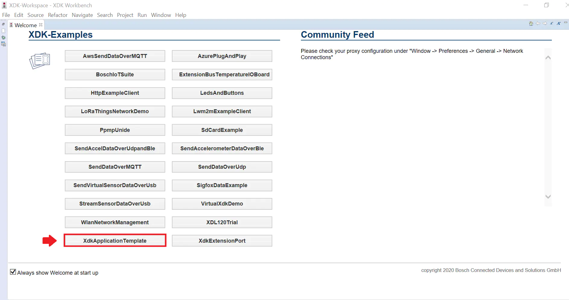
Open Workbench and you will get welcome page.

Go to XDK –Examples then select XdkApplicationTemplate
Go to source folder and edit AppController.c and AppController.h
Do below changes @ AppController.c
Include below header in the interface header section
Interface header section
#include “XDK_Sensor.h”
Add below define in the constant definition section.
Constant definition section
#define XDK_APP_DELAY UINT32_C(1000)
Configure the noise sensor by populating the below struct detail for noise sensor and add it in the local variables section
global variables section
  static Sensor_Setup_T SensorSetup =
  {
     .CmdProcessorHandle = NULL,
     .Enable =
        {
           .Accel = false,
           .Mag = false,
           .Gyro = false,
           .Humidity = false,
           .Temp = false,
           .Pressure = false,
           .Light = false,
           .Noise = true,
         },
  };/**< Sensor setup parameters */
Enable the sensor set up @ AppControllerSetup( ) by the below code sample code
Set up the sensor
static void AppControllerSetup(void * param1, uint32_t param2)
{
    BCDS_UNUSED(param1);
    BCDS_UNUSED(param2);

    SensorSetup.CmdProcessorHandle = AppCmdProcessor;
    Retcode_T retcode = Sensor_Setup(&SensorSetup); /* Key function to set up the sensor */
    if (RETCODE_OK == retcode)
    {
        retcode = CmdProcessor_Enqueue(AppCmdProcessor, AppControllerEnable, NULL, UINT32_C(0));
    }
    if (RETCODE_OK != retcode)
    {
        printf("AppControllerSetup : Failed \r\n");
        Retcode_RaiseError(retcode);
        assert(0); /* To provide LED indication for the user */
    }
}
Enable the sensor @ AppControllerEnable ( ) using below code snippet.
Enable the sensor
static void AppControllerEnable(void * param1, uint32_t param2)
{
    BCDS_UNUSED(param1);
    BCDS_UNUSED(param2);

    Retcode_T retcode = Sensor_Enable();  /* Key function to Enable the sensor */

    if (RETCODE_OK == retcode)
    {
        if (pdPASS != xTaskCreate(AppControllerFire, (const char * const ) "AppController", TASK_STACK_SIZE_APP_CONTROLLER, NULL,          TASK_PRIO_APP_CONTROLLER, &AppControllerHandle))
        {
            retcode = RETCODE(RETCODE_SEVERITY_ERROR, RETCODE_OUT_OF_RESOURCES);
        }
    }
    if (RETCODE_OK != retcode)
    {
        printf("AppControllerEnable : Failed \r\n");
        Retcode_RaiseError(retcode);
        assert(0); /* To provide LED indication for the user */
    }
    Utils_PrintResetCause();
}
Get the sensor data @ AppControllerFire( ) using the below code sample code
Get the sensor data
static void AppControllerFire(void* pvParameters)
{
   BCDS_UNUSED(pvParameters);

   Retcode_T retcode = RETCODE_OK;
   Sensor_Value_T sensorValue;

    while (1)
    {
      memset(&sensorValue, 0x00, sizeof(sensorValue));

      retcode = Sensor_GetData(&sensorValue); /* Key function to get the sensor data */
      if (RETCODE_OK == retcode)
      {
       if (SensorSetup.Enable.Noise)
       {
         printf("Noise Sensor RMS Voltage :Vrms = %f \r\n", sensorValue.Noise);
       }
      }

      if (RETCODE_OK != retcode)
      {
       Retcode_RaiseError(retcode);
      }
      vTaskDelay(pdMS_TO_TICKS(APP_CONTROLLER_TX_DELAY));
     }
   }
- Do below changes @ AppController.h
Add below define in the constant definition section
Constant definition section
#define APP_CONTROLLER_TX_DELAY UINT32_C(1000)
Compile the code and get the binary to flash.
Connect the XDK with PC via USB then switch ON XDK.
You will get Noise sensor data in the XDK console as below (sample data)
Sample log
INFO | XDK DEVICE 1: Noise Sensor RMS Voltage :Vrms =  0.005060
INFO | XDK DEVICE 1: Noise Sensor RMS Voltage :Vrms =  0.003735
INFO | XDK DEVICE 1: Noise Sensor RMS Voltage :Vrms =  0.002346
INFO | XDK DEVICE 1: Noise Sensor RMS Voltage :Vrms =  0.002981
INFO | XDK DEVICE 1: Noise Sensor RMS Voltage :Vrms =  0.002657
INFO | XDK DEVICE 1: Noise Sensor RMS Voltage :Vrms =  0.005853
INFO | XDK DEVICE 1: Noise Sensor RMS Voltage :Vrms =  0.006703
INFO | XDK DEVICE 1: Noise Sensor RMS Voltage :Vrms =  0.002534
INFO | XDK DEVICE 1: Noise Sensor RMS Voltage :Vrms =  0.003863
INFO | XDK DEVICE 1: Noise Sensor RMS Voltage :Vrms =  0.002784
INFO | XDK DEVICE 1: Noise Sensor RMS Voltage :Vrms =  0.004914
INFO | XDK DEVICE 1: Noise Sensor RMS Voltage :Vrms =  0.003144
INFO | XDK DEVICE 1: Noise Sensor RMS Voltage :Vrms =  0.011946
INFO | XDK DEVICE 1: Noise Sensor RMS Voltage :Vrms =  0.002577
INFO | XDK DEVICE 1: Noise Sensor RMS Voltage :Vrms =  0.003167
INFO | XDK DEVICE 1: Noise Sensor RMS Voltage :Vrms =  0.003795
INFO | XDK DEVICE 1: Noise Sensor RMS Voltage :Vrms =  0.014004
INFO | XDK DEVICE 1: Noise Sensor RMS Voltage :Vrms =  0.007473
INFO | XDK DEVICE 1: Noise Sensor RMS Voltage :Vrms =  0.012506
INFO | XDK DEVICE 1: Noise Sensor RMS Voltage :Vrms =  0.044059
INFO | XDK DEVICE 1: Noise Sensor RMS Voltage :Vrms =  0.002375
INFO | XDK DEVICE 1: Noise Sensor RMS Voltage :Vrms =  0.011065
INFO | XDK DEVICE 1: Noise Sensor RMS Voltage :Vrms =  0.002915
INFO | XDK DEVICE 1: Noise Sensor RMS Voltage :Vrms =  0.002955