Overview
Intended Use
The XDK 110 Cross-Domain Development Kit is a prototyping platform for Internet of Things (IoT) use cases. It works with Windows 7 or higher.
Included in Delivery
- XDK 110 Development Kit with Lithium Ion Battery
- Extension board with cable; 10 cm, 26 pin
- Micro USB 2.0 connector cable
- Mounting plate and screws
Sensors
| Name | Type |
|---|---|
| BMA280 | Accelerometer |
| BMG160 | Gyroscope |
| BMM150 | Magnetometer |
| BMI160 | Accelerometer/Gyroscope |
| BME280 | Humidity/Pressure/Temperature |
| AKU340 | Ambient Noise |
| MAX44009 | Ambient Light |
Data storage
- Micro-SD card slot
Communication
| Name | Type |
|---|---|
| Cable | USB 2.0 |
| Wireless | Bluetooth; Wireless LAN |
| LED | 1x green, 1x yellow, 1x orange, 1x red |
The LED Red, Orange and Yellow can be controlled in application mode.
Technical Specifications
| Name | Value |
|---|---|
| Temperature Range | -20 - 60 °C operating, 0 - 45 °C charging |
| Humidity | 10 - 90 %, non condensing |
| IP Rating | IP 30 (IEC 60529) |
| Flammability classification | HB (IEC 60695-11-10/-20; CSA C 22.2) |
| Voltage | 5 V DC |
| Charging Current | 500 mA maximum |
| Communication (cable) | USB |
| Wireless LAN | IEEE 802.11 b/g/ |
| Bluetooth 4.0 | IEEE 802.15.1 |
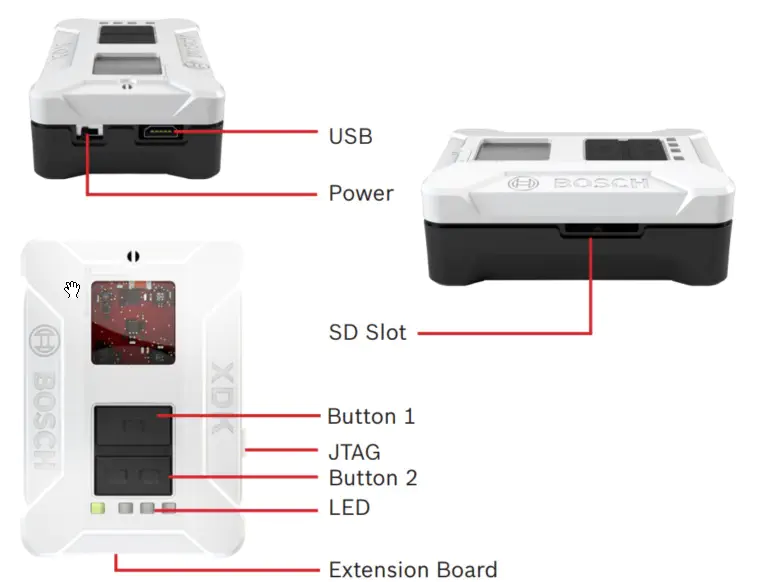
Connectors, Buttons and LED

Start-up and Software
The software for the XDK is available online. You can download the software from Downloads to get the latest software package and demos.
Download and Installation
Download the software package “XDK Workbench” from Downloads and start the installer. The software package contains all necessary components. Program examples, demos and a Toolbox are included.
Connecting XDK 110
Connect the USB cable that was included in delivery with the USB connector of your PC and the Micro-USB Connector of the XDK.
NOTICE
Functional Limitations
The device can be impaired or damaged if the power source is inadequate.
- Do not use cables > 3 m
- Use only certified USB power adapters
The XDK 110 uses the LED to show the following states:
After XDK 110 has been switched on the first time, a running light demo will start.
LED Green:
The green LED shows the charging status and cannot be controlled by software.
| State | Meaning |
|---|---|
| Continuous | Charging/Charging suspended by thermal loop |
| Flashing | Safety timers expired |
| Off | Charging done/Recharging after termination/IC disabled or no valid input power/Battery absent |
The following LED are active if the XDK is in bootloader mode:
LED Yellow:
| State | Meaning |
|---|---|
| Continuous | Bootloader mode active and USB connected; Driver loaded |
LED Red:
| State | Meaning |
|---|---|
| Continuous | Bootloader mode active |
| Flashing 5x | No valid application detected; XDK remains in bootloader mode |
Connecting the Extension Board “XDK Gateway”

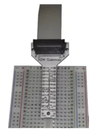
Connect the 26-pin cable that was included in delivery with the extension board to the 26-pin connector of the XDK 110. The extension board offers a simple way to implement additional functions. It is optimized for the use of breadboards.
Connector Pin Assignment on the Extension Board
| Connector Pin | MCU-Pin | Suggested Use | Connector Pin | MCU-Pin | Suggested Use |
|---|---|---|---|---|---|
| A1 | PA0 | TIM0_CC0 | B1 | PB9 | UART1_TX (U1_TX) |
| A2 | PC0 | TIM0_CC1 | B2 | PB10 | UART1_RX (U1_RX) |
| A3 | PC1 | TIM0_CC2 | B3 | PB2 | UART1_RTS |
| A4 | PC2 | TIM0_CDTI0 | B4 | PF6 | UART1_CTS |
| A5 | PC3 | TIM0_CDTI1 | B5 | PB4 | US2_MISO (U2_RX) |
| A6 | PC4 | TIM0_CDTI2 | B6 | PB3 | US2_MOSI (U2_TX) |
| A7 | PC8 | TIM2_CC0 | B7 | PB5 | US2_SCK (US2_CLK) |
| A8 | PC9 | TIM2_CC1 | B8 | PD8 | US2_CS (EXT_CS) |
| A9 | PC10 | TIM2_CC2 | B9 | PB11 | I2C1_SDA |
| A10 | PD6 | ADC0_CH6 | B10 | PB12 | I2C1_SDL |
| A11 | PD5 | ADC0_CH5 | B11 | 2V5 | Power Limit 100Â mA continuous/peak |
| A12 | PA1 | GPIO | B12 | 3V3 | Power Limit 100Â mA continuous/peak |
| A13 | PE2 | GPIO | B13 | GND | Power |
Errata
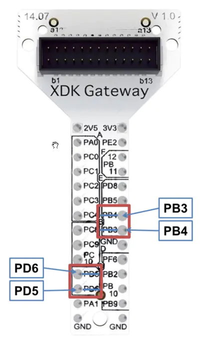
Unfortunately, there is an error in the labelling of the “XDK Gateway” (Version V1.0) extension board delivered with XDK. Some of the pins names were swapped. The correct pin assignment is shown in the picture below. We apologize for any inconvenience caused by this.

Getting Started
- Start the software “XDK Workbench”
- The “Welcome” screen will appear
- If an XDK is connected, the XDK symbol will appear
- Create your application
- Click on the “Flash” Button. Your application will be transferred to the XDK
- Check the output of the XDK by using the console of the “XDK-Workbench”
Flashing the XDK 110
The XDK 110 can only be programmed while in bootloader mode. To enter bootloader mode, press the “Flash” button. The software puts the XDK 110 in bootloader mode, flashes the program and reboots. If the software does not put the XDK 110 in bootloader mode, this can be done manually:
- Switch off the XDK 110
- Press Button 1
- Hold down Button 1 and switch the XDK 110 back on
The red LED will light up. If a USB connection is already established, the yellow LED will also light up. Press the “Flash” button.
Demos
The software package contains three demos:
- Data Logger: Storage of sensor data on a Micro-SD card
- Virtual XDK: Renders an XDK that is connected to a tablet via Bluetooth. The XDK on the tablet moves analogously to the real XDK
- Sensor Monitor: Shows a 2-D view of the raw sensor data (samples over time)
Toolbox
The Toolbox contains various function blocks and und algorithms, like filters, FFT (Fast Fourier Transform) and more. For example, the toolbox can help determine the spatial position of the XDK 110 by using the raw data from the gyroscope and the accelerometer.
API Documentation
The API documentation can be opened using the “Help” function of the “XDK-Workbench”.
Acessories
Additionally, the J-link adapter “J-Link 9-Pin Cortex-M Adapter” can be purchased from Segger (http://www.segger.com). The adapter facilitates using JTAG to debug the program on the XDK 110. While ordering, refer to XDK 110 to get the right adapter.
Radiofrequency Radiation Exposure and further Information
The radiated output power of the device is far below the FCC radio frequency exposure limits. Nevertheless, the device shall be used in such a manner that the potential for human contact during normal operation is minimized.
NOTICE
This device complies with Part 15 of the FCC Rules and with Industry Canada licence-exempt RSS standard(s). Operation is subject to the following three conditions:
- This device may not cause harmful interference, and
- This device must accept any interference received, including interference that may cause undesired operation
- The minimum distance between body and device should be 20 cm
Le présent appareil est conforme aux CNR d’Industrie Canada applicables aux appareils radio exempts de licence. L’exploitation est autorisée aux trois conditions suivantes:
- l’appareil ne doit pas produire de brouillage, et
- l’utilisateur de l’appareil doit accepter tout brouillage radioélectrique subi, même si le brouillage est susceptible d’en compromettre le fonctionnement
- La distance minimum entre appareil et corps est 20 cm