Startup
This section covers the main functionalities of the XDK-Workbench’s user interface.
- Opening The Workbench
- Workspace View
- Editor
- Console
- XDK Operating Modes
- Bootloader Mode
- Application Mode Startup Guide
- Application Template
Opening The Workbench
Start the XDK-Workbench by clicking on the XDK icon on your desktop. The default path of the application is located in C:\XDK-Workbench\XDK-Workbench.exe. During the startup a splash screen appears. The welcome screen will be shown afterwards.
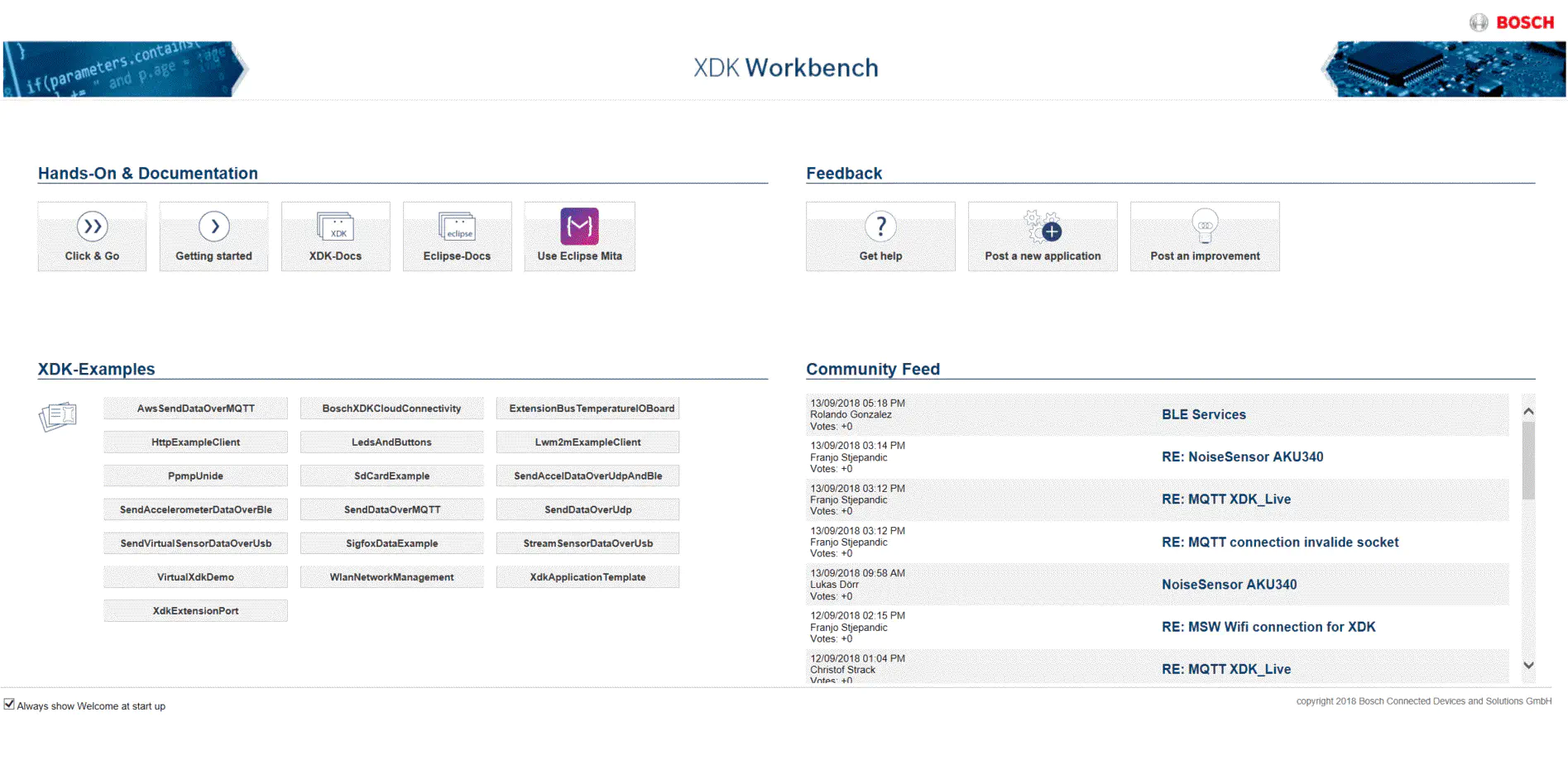
The welcome screen is sectioned in three parts: Hands-On & Documentation (upper left), Feedback (upper right) and the XDK-Examples (lower left).
Hands On and Documentation
This section contains four buttons.
- Click&Go - Access the workspace set up for a quick start
- Getting Started - The shortcut to the XDK forum for community interaction
- XDK Docs - This button will open the documentation
- Eclipse Docs - This button will open the Eclipse help (the XDK-Workbench is based on Eclipse)
Feedback
Clicking the respective button will take you to the matching XDK community forum section to get help, to post a new application or to post an improvement. Inside the community you will find hints, tips and tricks and you can get in touch with other developers.
XDK Examples Overview
The XDK comes with a variety of application examples. Choose one example and click on it. The chosen example will be imported into the workspace. The following examples are currently included:
- Basics
- XdkApplicationTemplate - This is an empty template serving as a starting point for new projects
- LedsAndButtons - This example contains a showcase for the use of LEDs and buttons.
- SdCardExample - This example contains the showcases for the use of the SD card file system.
- Networking
- HttpExampleClient - This example shows how to use the network stack to perform an HTTP client request.
- PpmpUnide - This example demonstrates the XDK’s capabilities to use the production performance management protocol to serialize the XDK’s sensor data and to send the sensor data over HTTP/S to an HTTP server which post-processes this data.
- Lwm2mExampleClient - This example demonstrates how to register with a LWM2M server including the standard LWM2M objects. Unencrypted and encrypted communication is both supported.
- BoschXDKCloudConnectivity - This example demonstrates how to register with a LWM2M server, including the standard LWM2M and IPSO Alliance sensor objects with very little necessary editing. The implementation supports both insecure and secure connections, which can be chosen accordingly.
- AwsSendDataOverMQTT - The example contains the functionality to send the XDK’s sensor data through the MQTT protocol to the AWS IoT core.
- SendDataOverMQTT - The example demonstrates the capabilities of the XDK to send sensor data through the MQTT protocol to a configured MQTT broker which post-processes this data.
- SendDataOverUdp - This example demonstrates how to send arbitrary data over WLAN as a UDP broadcast.
- WlanNetworkManagement - This example demonstrates how to use the XDK WLAN abstraction to scan for networks, join networks, set a static IP address or dynamically obtain an IP address via DHCP.
- Sensors
- SendAccelerometerDataOverBle - This example streams raw accelerometer data from the BMA280 acceleration sensor via Bluetooth Low Energy (BLE). The Alpwise Data Exchange Profile is used; Alpwise iOS/Android app is required. Send
startto the XDK, so that streaming of data begins. - SendVirtualSensorDataOverUsb - The example will print out raw data from all available physical sensors. The example captures the sensor data of all sensors in one cycle.
- StreamSensorDataOverUsb - This example will print out data from the virtual sensors over the USB port. The particular sensor can be selected in the source code.
- SendaccelDataOverUdpAndBle - If you want to use WLAN and BLE, here is a demo for this. This example demonstrates how to read sensor values from the BMA280 acceleration sensor and send the data over WLAN (UDP broadcast) and Bluetooth Low Energy via the Alpwise Data Exchange Profile. Use either your Android or iOS mobile phone (see Android Play Store or iOS App Store) to connect to XDK and receive the data. Send
startto the XDK via Bluetooth Low Energy, so that streaming of data begins. - VirtualXdkDemo - This example demonstrates the XDK’s sensors, using an Android/iOS app, to which the XDK sends its data using BLE. The app visualizes the data in real time, allowing for a great presentation of the XDK’s features.
- SendAccelerometerDataOverBle - This example streams raw accelerometer data from the BMA280 acceleration sensor via Bluetooth Low Energy (BLE). The Alpwise Data Exchange Profile is used; Alpwise iOS/Android app is required. Send
- Extension Bus
- XdkExtensionPort - This example demonstrates the capabilities when using the Extension Bus of the XDK. It provides the possibility to communicate with external attached devices over UART, SPI, I2C or simply over GPIO.
- ExtensionBusTemperatureIOBoard - This example contains the functionality to connect to the extension temperature IO board MAX31865 to print out temperature data from the PT100.
- SigfoxDataExample - This example contains the functionality to send out sensor data over an external Sigfox XDK extension into the Low Power WAN (LPWAN) provided by Sigfox.
Workspace View
Let us get started with the workspace view.
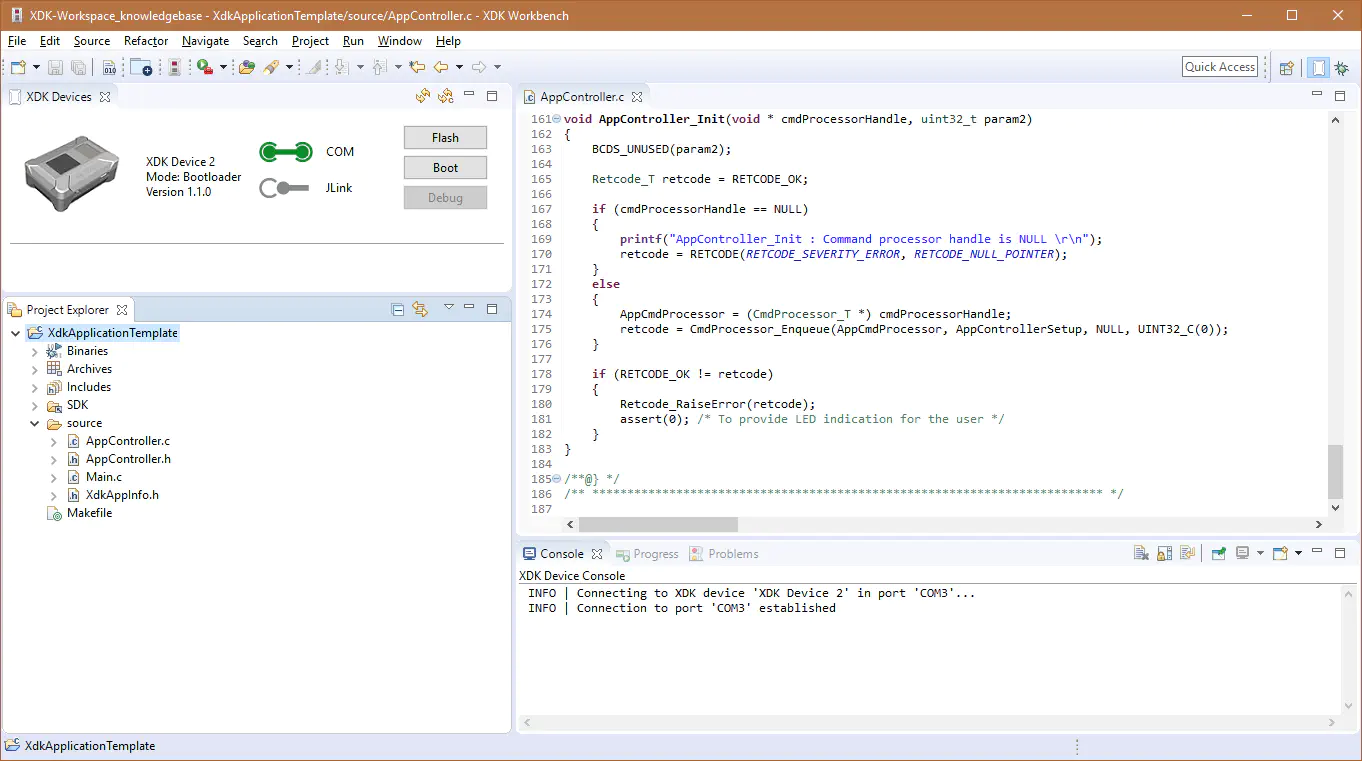
The default XDK-Workbench setup is split into four main tiles per default: XDK Devices (upper left), Project Explorer (lower left), Editor (upper right) and Console (lower right). The menu bar is located at the top of the window as usual.
Each tile can be maximized or minimized by clicking on the respective symbol on the tile. Resizing is possible by changing the position of the tile borders. You can change the perspective by clicking on the Open Perspective button.
Menu Bar

The menu bar contains all necessary functions of the XDK-Workbench. There is a classic menu structure and a symbols bar. Some entries are available only in a suitable context (e.g. refactor). The symbols are only active highlighted if a matching context exists.

- Project/Other - Same as
File -> New, opens the Project Wizard. - Save/Save All - Saves (all) files shown in the editor.
- Build All - Compiles all files (of all open projects).
- Opens C Project Wizards - Shows all examples per default.
- Opens the Welcome Page.
- External Tools - Click on the black arrow for more options. Same structure as in the Run menu above.
- Open Element - Opens the element menu.
- Search - Opens the File/C++ search menu, can also be reached via Search above.
- Toggle Mark Occurrences - Marks occurrences of a search in the editor.
- Next/Previous Annotation - Jumps to the next/previous annotation. Choose the annotation type by clicking on the black arrow.
- Last Edit Location - Jumps and sets the cursor to the last edited position.
- Forward…/Back to… - Switches between the register cards in the editor.

- Quick Access - Shows the possibilities of the XDK-Workbench by simply typing in character or numbers, sorted by category.
- Open Perspective - Changes the XDK-Workbench view according to the chosen perspective.
- After choosing a different perspective, the matching symbol appears right from the
Open Perspectivebutton for faster access. The buttons disappear with right-click/close
XDK Devices
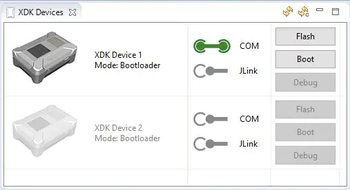
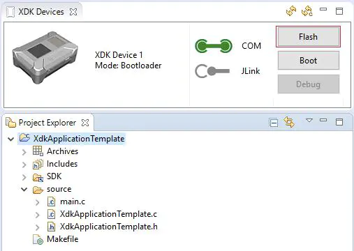
The XDK devices list shows a list of all XDKs that got connected during the current session in the XDK-Workbench. The three buttons on the right allow to flash, boot or to debug the device. For activating the debug mode, the JLink adapter (sold separately here) must be connected. Right-clicking on the XDK will open the context menu. You can choose Go to Bootloader and Flash Bootloader. Also you can rename the XDK device here, as seen in the following picture.
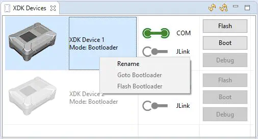
The COM- and JLink buttons in the device list can also be manually activated or deactivated. The COM button enables the current connection between the XDK and the PC. The JLink button enables the current connection over the JLink of the XDK to the PC. What a JLink is and does will be explained later in this chapter.
Flash Button
Select a project from the Project Explorer or import an example from the XDK welcome screen. Press the Flash button. The XDK-Workbench then compiles the project and puts the XDK into bootloader mode. The compiled project is now transferred to the XDK, which boots automatically on completion.
Boot Reboot
The button is context-sensitive and can change between Boot and Reboot, depending on the current mode of the XDK. By pressing the Boot button the XDK boots from bootloader to application mode. By pressing the Reboot button, the XDK switches from application mode to bootloader mode.
Debug
For debugging a JLink adapter is required. Choose a previously compiled project. The XDK-Workbench configures the debug configuration automatically. The binary is downloaded to the XDK and the debugger starts. The XDK-Workbench proposes to switch to debug perspective.
XDK Device Information
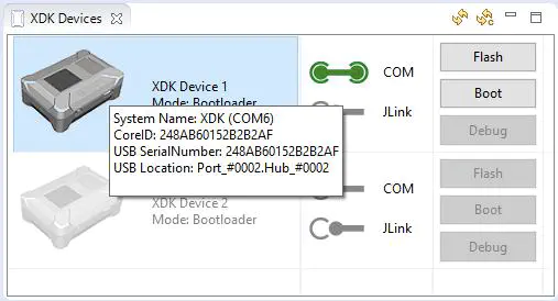
To get some system relevant information like the connected XDK’s CoreID or the USB serial number, you can mouse over a device. A window will appear and display the information. The CoreID is unique for each XDK and is based on its micro controller ID.
Project Explorer
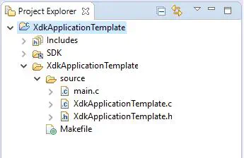
The Project Explorer stores all current XDK projects. It allows the creation of new projects and the implementation of example projects from the welcome screen. It is also possible to import and export projects from and to the XDK community.
Creating a new Project
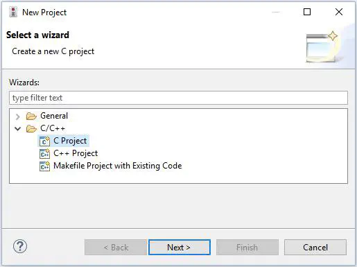
It is possible to create new projects in the Project Explorer. For this you have to right-click in the Project Explorer area, Select New -> Select Project.
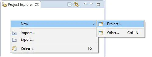
Now you have to choose between certain project types. It is recommended to create a C project.
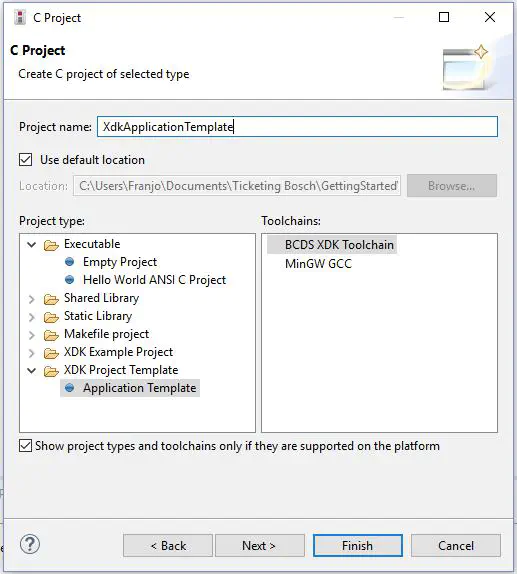
Open XDK Project Template and then select Application Template. This will include the required BCDS XDK toolchain. The toolchain is required to compile and flash an application onto the XDK.
Editor
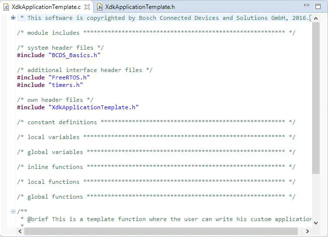
The editor area of the XDK-Workbench allows entering and editing of code lines. More functions are available by using the context menu.
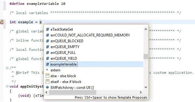
One of the most useful features of the XDK-Workbench is code autocompletion. Start typing the character and complete the name with ctrl + space. With this shortcut it can be avoided to type long variable names. Additionally it is a convenient way to find variables and functions you want to use from the included libraries.
Console
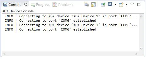
The console tab shows an overview of the status of the XDK-Workbench, allows sending data to the XDK and shows output coming from the XDK via USB. Buttons are available on the upper right side of the tile, depending on the current status. These buttons contain functions like go to next error, clear console, etc. There are two additional tabs. Progress shows the current status of e.g. flashing.
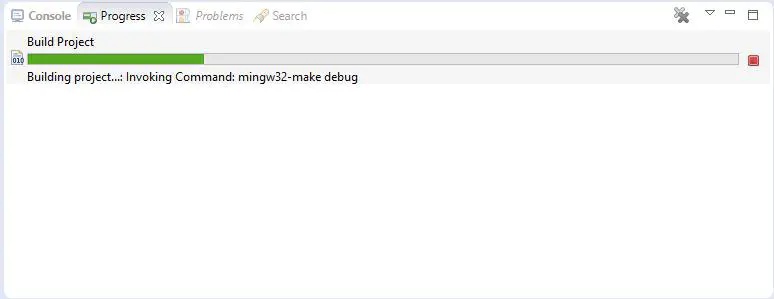
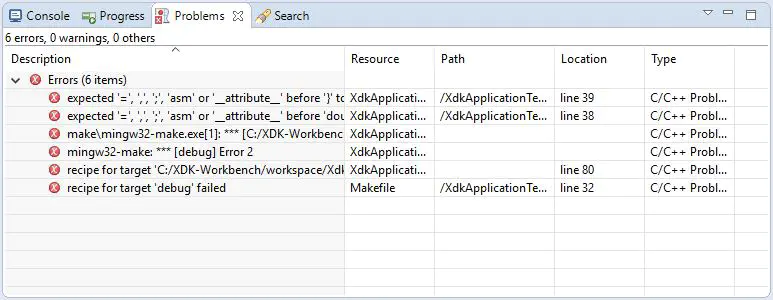
You can cancel the operation by clicking on the red button on the right side of the progress bar. The Problems tab displays existing problems detected by the XDK-Workbench.
XDK Operating Modes
This chapter describes the different operation modes of the XDK, how to determine in which mode the XDK is and how to switch between them. Please note that in normal operation, the XDK-Workbench will automatically detect the mode it currently is in. Furthermore, the XDK-Workbench will try to automatically perform the mode switch that is required for its correct function. However, there may be certain situations in which the automatic detection or the automated switching does not work. In general, the XDK knows the following modes
- Bootloader Mode
- Application Mode
- Assertion
- Stack Overflow
Bootloader Mode
The XDK bootloader is stored in the first 64 kB of XDK’s flash memory. When the bootloader is no longer present or becomes corrupted, an update or recovery is only possible via the JLink Adapter. The bootloader allows uploading XDK applications via USB (see XDK Bootloader in the XDK General for further information). The bootloader is write-protected and can only be overwritten or updated using the JLink Adapter (sold separately here) via the XDK-Workbench.
When powering up, the XDK will automatically go into the bootloader mode, which is indicated by the red LED. If the XDK finds a valid application, the bootloader will automatically turn off the red LED and start the application. If no valid application is found or the XDK is forced to go into bootloader mode, the yellow LED indicates if the XDK is successfully connected to a PC. Once the red and yellow LEDs are solid on, the XDK shows up in the device view of the XDK-Workbench and can be programmed.
The XDK can be set into bootloader with a useful feature of the XDK-workbench. Right-click on the XDK and select Go to Bootloader. In the case that the XDK does not respond (and is possibly not even recognized over USB), you can manually force the XDK into bootloader mode via the approach 1 below.
Approach 1
- Switch off the XDK
- Press and hold Button 1
- Turn on the XDK
- Release Button 1 as soon as red LED turns on
This approach is the “last resort” for when the XDK does not respond after turning it on. Even if the XDK is not recognized over USB, approach 1 will work. There are two more ways to set the XDK into bootloader mode.
Approach 2
- Get XDK into application mode (typically by turning it on)
- Connect it to your PC
- Start XDK Workbench
- Right-click on your XDK in the XDK Device View and select
Go to Bootloader
The second approach will set a flag in the user page of the MCU of XDK. When the XDK reboots, the bootloader reads the flag and engages itself. Only after booting an application, the flag is reset.
Approach 3
- Get XDK into application mode (typically by turning it on)
- Connect it to your PC
- Connect to XDK with a serial terminal program (see
XDK_USB_DEVICE_HANDLING_Terminal) - Send the following string:
#reBoot$ - XDK will automatically reboot and go into the bootloader
This is technically the same as approach 2, but it is to mention that it is possible to send commands to the XDK via the serial interface.
Binary images uploaded via the bootloader must be transferred in the XMODEM-CRC format.
Application Mode Startup Guide
This simple guide is intended for developers who are going to develop applications for XDK, to know the basic startup procedure of the system before they start writing their application. The XDK software can be configured to start in two ways as described below. The configuration can be done using the BCDS_SYSTEM_STARTUP_METHOD macro present in the application makefile. By default the XDK is shipped with DEFAULT_STARTUP enabled. Refer the code block below representing the change.
export BCDS_SYSTEM_STARTUP_METHOD=CUSTOM_STARTUP
Default Startup
The main() function implemented in the SystemStartUp module will be the first C function executed during power ON and it does the following:
- EFM32 chip is configured to a proper state with the help of the library function exported by emlib.
- All interrupt sources are configured to maximum priority to ensure that ISR runs at highest priority.
- System peripherals like GPIO, I2C and USB are initialized to a proper state.
- GPIO pins are configured to their default value.
- The user page module is initialized. It is used to save configuration information like Wi-Fi MAC address, Bluetooth MAC address, etc., in the user page area of flash.
- Creates a default application specific initialization timer and start it.
- Gives control to the operating system by starting the task scheduler of FreeRTOS.
Custom Startup
The custom startup procedure will exclude steps 3 to 5 of the default startup procedure described above to give users the flexibility in initializing system peripherals. Users can choose to initialize and configure the peripherals which they want to use in their application. If the custom startup procedure is configured, users have to ensure that the GPIO pins they are using are initialized to a proper default state. In both of the above configurations XDK’s SystemStartUp module will schedule a default application-specific initialization timer AppController_Init() which will run in the timer task context with task priority 2.
Note: main.c is required to start up the FreeRTOS operating system. All code implementations will take place in additional interface header .h files and implementation .c files. Please view the section Including C++ code in Platform Architecture for more information on how to add new interfaces to the XDK.
Application Template
The XDK-Workbench provides a recommended project-template for own projects. This template is called XdkApplicationTemplate. It includes the BCDS XDK toolchain that is required to compile and flash a project to the XDK.
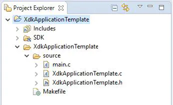
The XdkApplicationTemplate can be imported in two different ways. One is to import the template over the welcome screen by clicking on the example XdkApplicationTemplate. The other one is to generate the XdkApplicationTemplate as project as described in the chapter Project Explorer.